

In a stacked transformer core, the laminations meet at joints where the limbs connect to the yokes. Those joints are where magnetic flux has to cross from one lamination to another, and how they are designed shapes how the core is cut, stacked and assembled. Two broad approaches are common: conventional mitred joints with one or two overlapping layers, and step-lap joints in which the joint position steps across several laminations.
This article compares the two from a manufacturing point of view. It explains what changes in lamination cutting, programming and stacking when a manufacturer moves to step lap core cutting, so production and planning teams know what to expect. It does not set out transformer design rules or quantify performance. Core design decisions, including joint type and step configuration, belong to the transformer designer, and technical claims about losses should be reviewed by a qualified engineer for each design.
Joints in a Stacked Core
Stacked cores for power and distribution transformers are built from thin sheets of grain-oriented electrical steel, commonly called CRGO. Grain-oriented steel has its best magnetic properties along the rolling direction, so laminations are cut with their length in that direction. Where a limb meets a yoke, the direction of flux changes, and laminations are usually cut with angled ends, typically at 45 degrees, so the joint follows the change in direction. This is a mitred joint.
The question is how successive layers of laminations are arranged at that joint.
Conventional Mitred Joints
In a conventional arrangement, the joint position alternates between two positions from one layer, or group of layers, to the next. Each joint is overlapped by the lamination above and below it. The pattern is simple: a small number of lamination shapes and lengths, repeated through the stack.
From a production point of view, conventional joints mean:
- Fewer distinct lamination lengths per core
- Simpler cutting programs
- A simpler stacking sequence
Step-Lap Joints
In a step-lap arrangement, the joint position shifts by a small offset over several successive laminations, creating a staircase pattern before the sequence repeats. Instead of two alternating positions, there are several. The number of steps and the size of the offset are set by the core designer.
Step-lap joints are widely used in modern transformer cores because the stepped arrangement spreads the joint over a wider area. Valgo’s step-lap core cutting page describes how laminations are cut with alternating lengths so that the joints are staggered when stacked. Published studies have examined the effect on performance. For example, a master’s thesis from the University of Moratuwa analysing step-lap cores against conventional cores in distribution transformers reported lower core loss in the cores it studied. Results of that kind depend on the specific design, material and build quality, so they should not be treated as a general figure for every transformer.
What Changes in Lamination Cutting
More lamination lengths
Because each step moves the joint position, each step needs laminations of slightly different lengths. A core that needed only a few lamination types with conventional joints may need several times as many with step-lap joints. The cutting line has to produce each of these accurately and in the right order.
Tighter length control
The step offset is small, so length errors become proportionally more significant. If laminations are not cut to the intended lengths, the step pattern is disturbed and gaps or overlaps at the joint change. Accurate feeding and length measurement are therefore central to step-lap production.
Angled cuts and notches
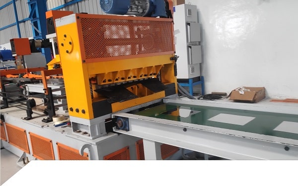
Mitred ends need accurate 45-degree cuts, and many core designs also include V-notches or holes for assembly. Valgo’s Transformer Core Cutting Machine line, for example, includes feeder, levelling, guide, V-notch, punching and shearing units, along with a stacker.
Burr and edge quality
Burr on lamination edges can create contact between adjacent laminations. Shear blade condition and setup matter on any core cutting line, and they matter more as the number of cut edges increases. Our earlier article on what transformer makers need from core cutting discusses burr, accuracy and material yield in the wider context of CRGO supply.
Programming and Controls
With step-lap joints, the cutting program becomes a sequence rather than a simple repeat. The control system needs to:
- Store the lamination lengths and step pattern for each core design
- Cut laminations in the order they will be stacked, or track them for later sorting
- Count laminations and steps accurately
- Allow quick changes between core designs
PLC-based control with stored programs makes this practical. Manual setting of each length would be slow and error-prone for step-lap work.
What Changes in Stacking and Assembly
Stacking is where step-lap joints place the greatest demand on the process. Each lamination must go into the right position in the right sequence, and the stack must stay aligned so the joints line up as designed.
- Stacking sequence: Laminations must follow the step pattern exactly. A single lamination out of sequence disturbs the joint.
- Alignment: Stacks must be kept square and aligned, often with guides or pins.
- Handling: Thin CRGO laminations should be handled carefully to avoid bending or damage that can affect magnetic properties.
- Automation: Automatic or robotic stacking reduces the risk of sequence errors and handling damage. Valgo’s core cutting line is available with manual or automatic precision stacking, and with robotic stacking that allows cutting and assembly in the same production phase.
Planning a Move to Step-Lap Production
For a manufacturer moving from conventional to step-lap cores, the key planning questions are:
- Which core designs will use step-lap joints, and how many steps and offsets do they require?
- What lamination widths and material thicknesses will be processed?
- Can the existing cutting line hold the length accuracy the step pattern needs?
- How will laminations be sequenced, counted and tracked?
- Will stacking be manual, automatic or robotic?
- How will burr be monitored and blades maintained?
- What training will operators need?
Conclusion
Choosing step-lap joints is a transformer design decision, but it has direct consequences on the shop floor. More lamination lengths, tighter length control, sequence-based programming and precise stacking all become part of daily production. Understanding those changes helps manufacturers plan the cutting and stacking capability they need before the first step-lap core goes into production.
To learn more about Valgo, read About Valgo Group. To discuss your lamination widths, core designs and stacking requirements, contact Valgo Group about your transformer core lamination line.
